01 / MECHANICAL DESIGN
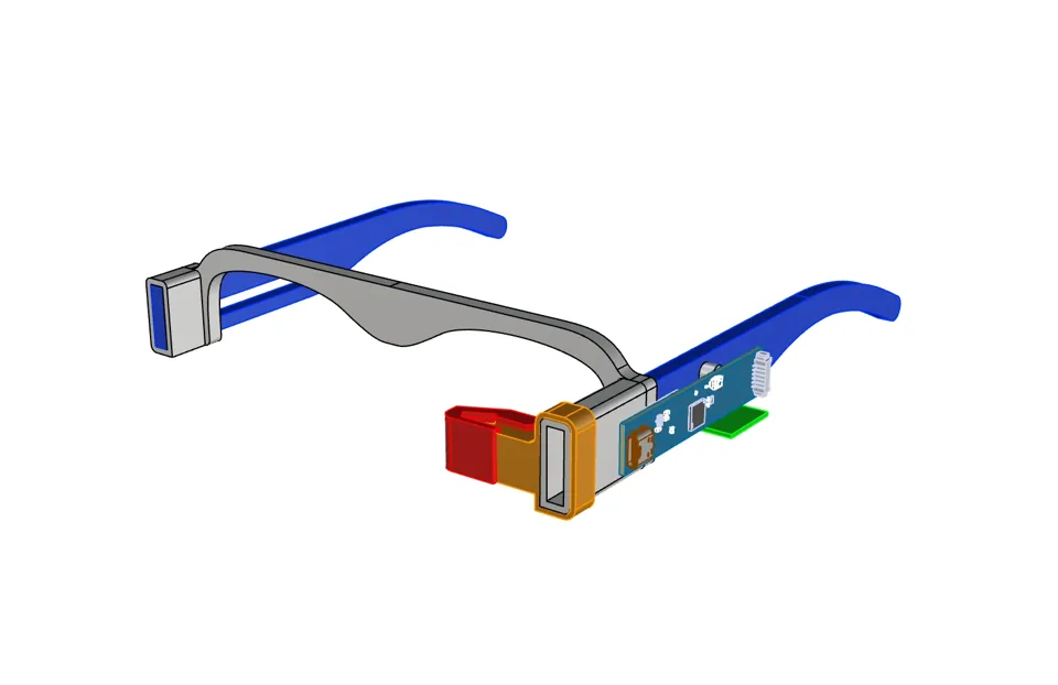
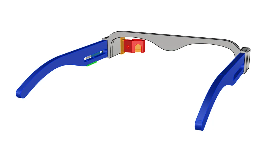
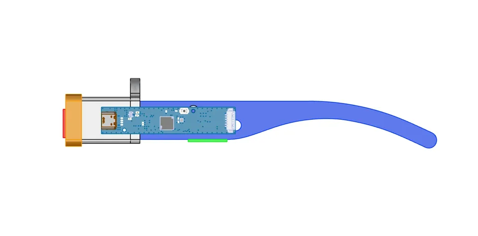
Wearable model
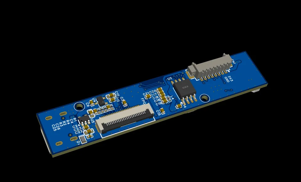
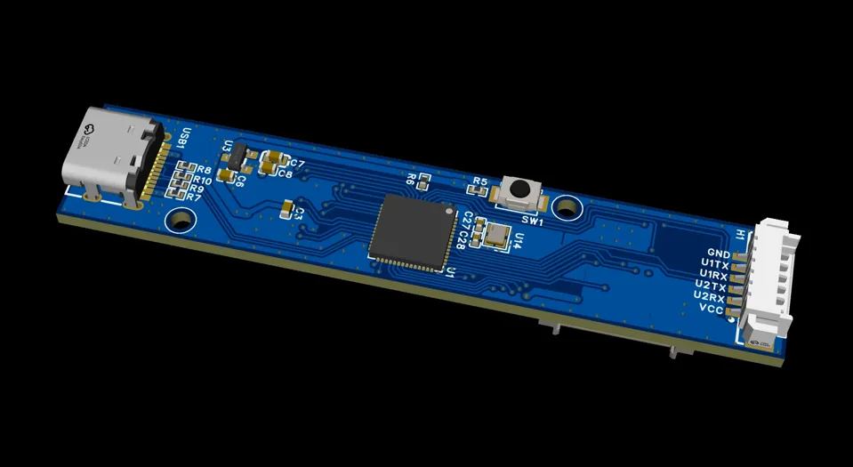
The camera and main board follow the glasses frame. All three CAD views are shown below.
INDEPENDENT PROJECT / ASSISTIVE TECHNOLOGY
An eye-tracking wheelchair interface that turns a glance into an intention—and asks before it moves.
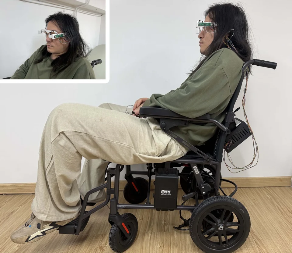
A joystick assumes that the person using it can reliably move a hand. I wanted to explore a different starting point.
GazeLink is my exploration of an eye-controlled wheelchair interface. A camera observes the user's eyes, an ESP32-S3 interprets the direction, and a voice module asks for confirmation before the system issues a motion command.
The design question is as much about intention as it is about sensing: looking somewhere should not automatically mean moving there.
Watch the eye move through four directions.
A five-second dwell leads to a voice request,
a simulated reply, and a motion command.
Look → dwell → voice request
→ simulated confirmation → move
An observation, not yet a command.
Command sent in this simulation
↗ Eye direction maps to forward, reverse, left and right.
↗ Voice requests and replies are simulated automatically.
↗ Five seconds is the example dwell, not a measured optimum.
Gaze and voice control, independent fall detection, and two DC-DC converters powered by the 36 V wheelchair battery.
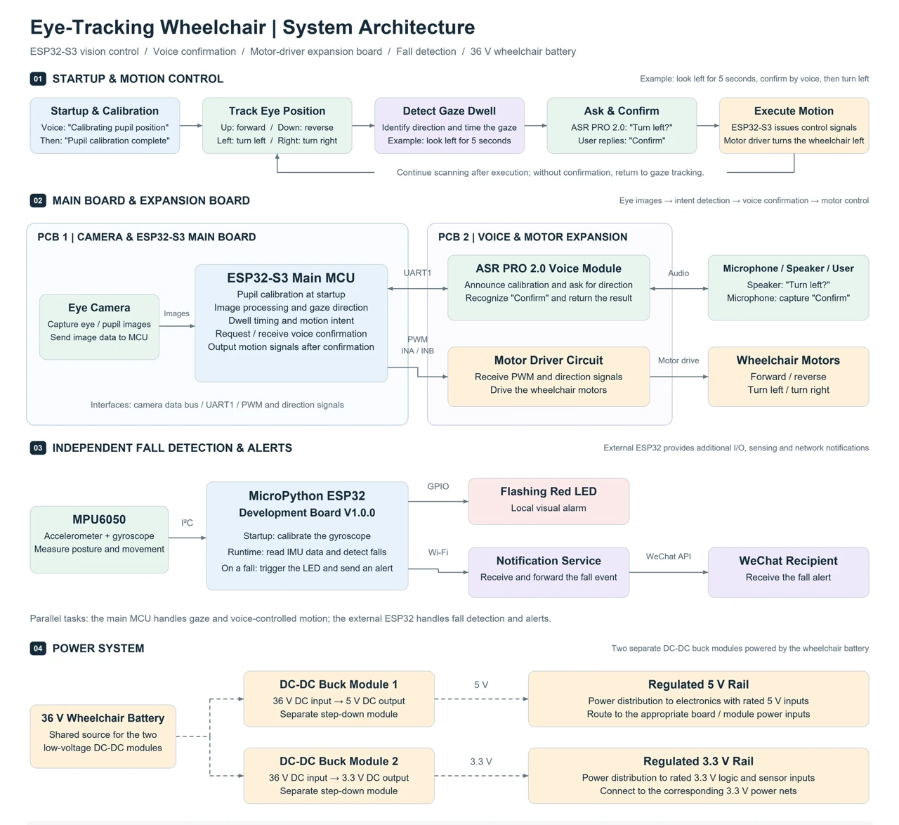
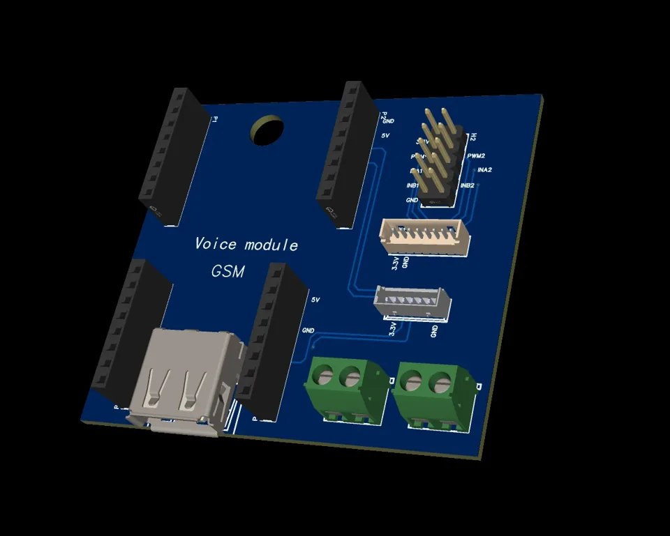
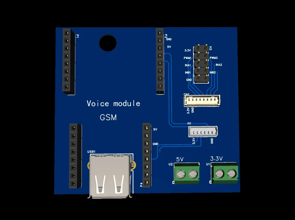
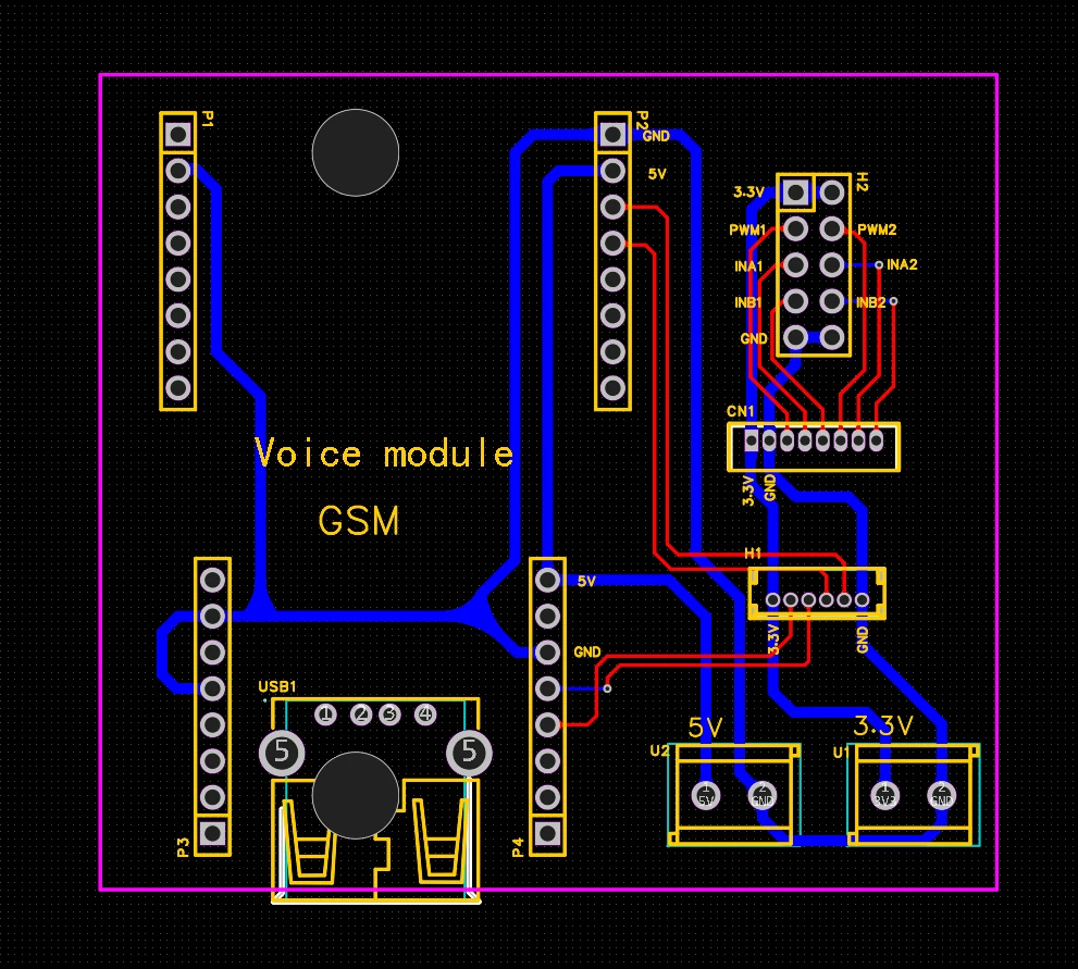
Connections between the main controller, expansion board, voice module, motor driver and sensors.
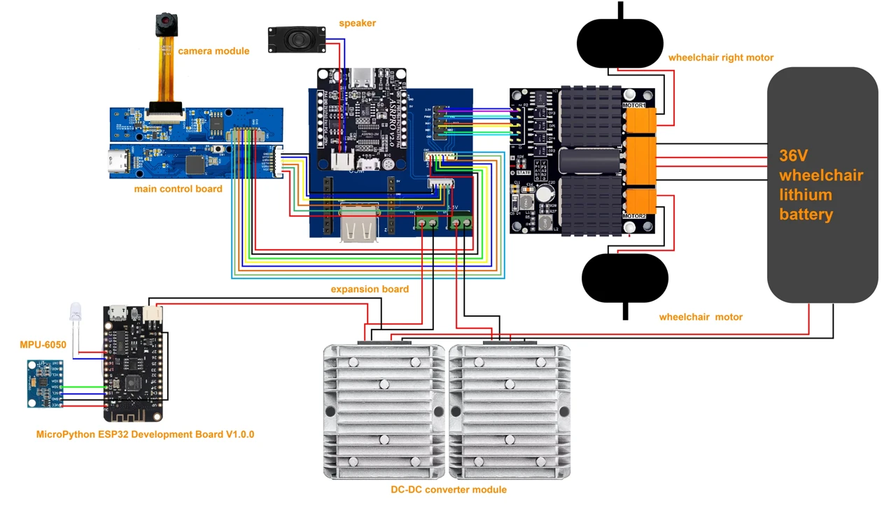
Custom circuit boards, a camera mounted on glasses, and a physical assembly that brings the subsystems together.
The camera and main board follow the glasses frame. All three CAD views are shown below.
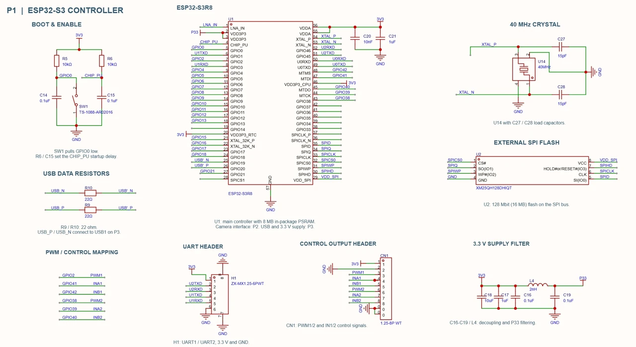
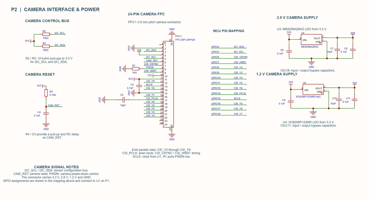
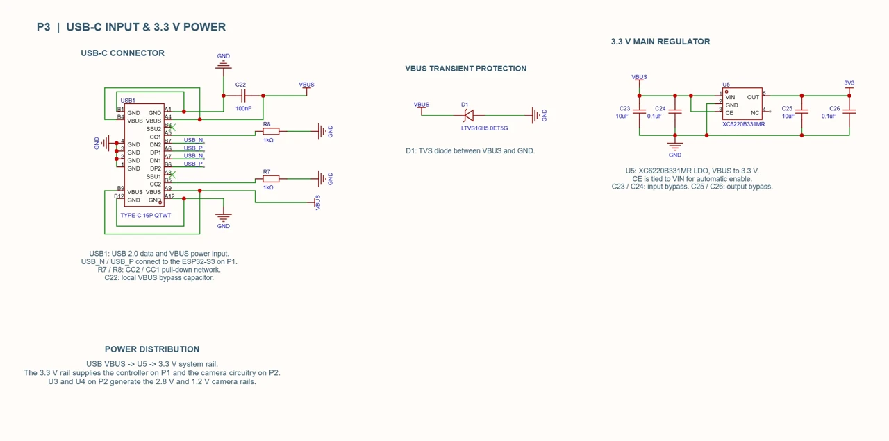
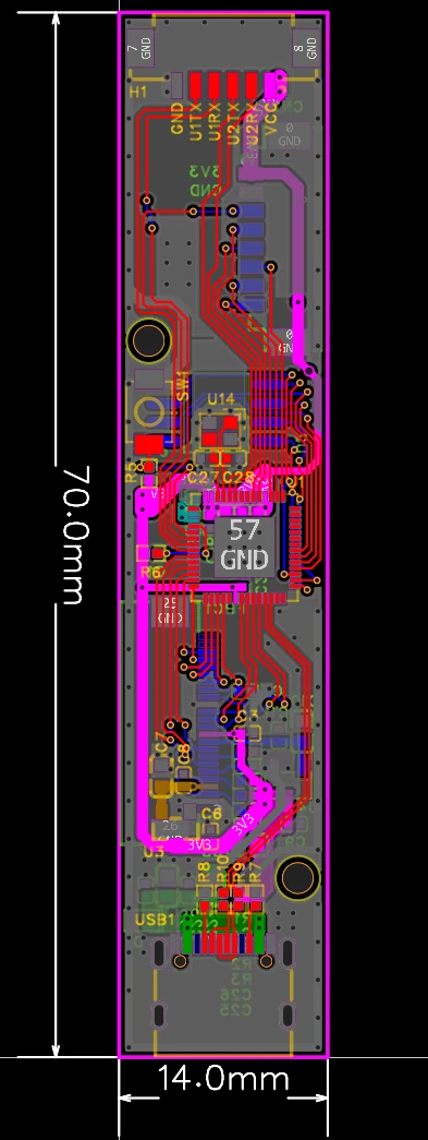
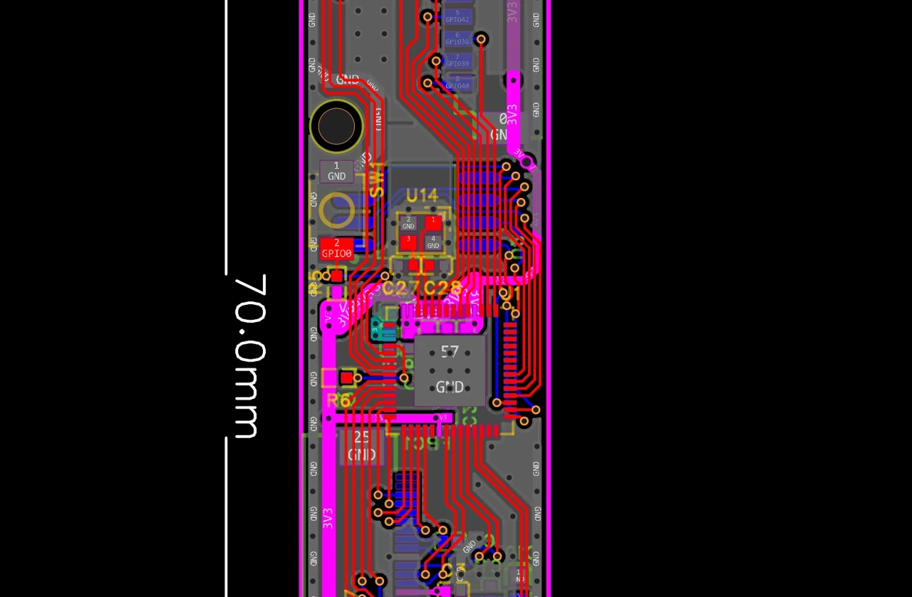
A narrow ESP32-S3R8 board integrates the camera interface, processing and control connections. Board outline: 70 × 14 mm.
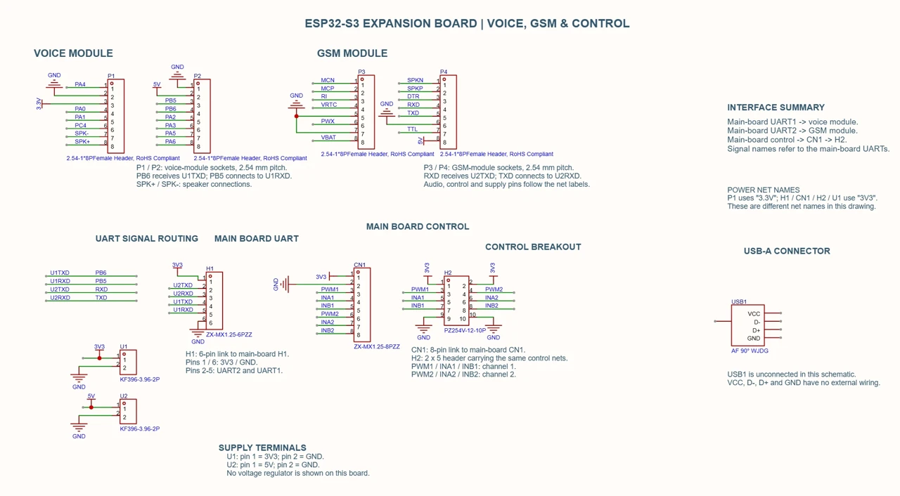
Connections for the ASR PRO 2.0 voice module, UART communication, motor-control signals and 5 V / 3.3 V power.
The narrow main PCB follows the glasses frame. Packaging is a design constraint, not an afterthought.
A dwell creates a request. Voice confirmation creates the command. This makes the decision explicit.
An additional ESP32 takes on the MPU6050, red indicator and notification path when main-controller I/O is limited.
The work moves between CAD, circuit design and the bench. These photographs document the physical prototype and its assembly.
The next challenge is to understand how the interface behaves outside an ideal interaction.
This project brings together a wearable, custom electronics and a proposed control sequence. The materials shown document design and assembly; they do not yet establish reliability in everyday wheelchair use.
Compare deliberate gazes with natural eye movements across lighting conditions. Measure false requests and missed directions.
Compare dwell durations and voice-recognition performance. Record task time, cancellations and confirmations before choosing a threshold.
Separate ordinary chair motion from simulated fall events. Check LED behavior, message delivery and network-loss conditions.
Evaluate camera placement and repeatable calibration. Define and verify stop behavior and fault handling on a controlled bench setup before any occupied-chair trial.